| Introduction |
To establish the identity of an unknown thread, certain tools and data
are necessary.
These charts and diagrams are a helpful
compilation of the data needed for the identification of most external
(male) threads from the three most popular thread systems in the world,
metric standards, U.S.A.(inch) standards, and the British (inch) standards.
Also this chart will outline the useful tools and procedures in attempting
to identify many other unknown threads.
These are the three basic steps to identify a thread:
step 1.Measure the major diameter of the male thread.
The major diameter
is the outside diameter (o.d.) of the male thread.
If you are trying to
identify an internal (female) thread these data charts may not contain
sufficient information.
step 2.Determine the number of threads per inch, or the number of threads
per millimeter (mm).
See the section for conversions from pitch to threads
per inch, and/or threads per centimeter.
An ideal way to accomplish
this measurement is with pitch gages or with thread gages (note: pitch
gages are quite inexpensive).
However, using a rule and taking a careful
count of threads is normally acceptable.
If you have access to thread
pitch gages your task will be greatly simplified.
step 3.Compare your measurements with the data charts.
Note: class of fit - such as the u.s.a. '2a/2b' or the metric '6g/6h' are
beyond the scope of the data included in these charts.
|
| Some helpful notes about threads; |
#1. The metric thread designation uses pitch in place of the more familiar
U.S.A. method of threads per inch (tpi).
Pitch is the distance in mm from
any one point on a thread to a corresponding point on the next thread, when
measured parallel to its axis.
2. Metric coarse thread does not need to have the pitch specified.
The
absence of a pitch specification indicates that the thread will be from
the coarse thread series.
3. The nominal diameter of metric pipe threads, both tapered and parallel
is the same as the major diameter (o.d.) of the thread.
However, the
U.S.A., British and Japanese nominal pipe thread diameters correspond to the
approximate inside diameter (i.d.) of the pipe or tube.
In section (a), all
these threads are listed in ascending major diameter size order.
This places
the U.S.A., British, and Japanese pipe threads among the thread diameters
which are larger than their nominal size.
4. Most metric countries in Europe and Asia use the British based inch
system (iso) for measuring pipe and tubing threads.
Some examples of these
thread designations follow:
Threads equivalent to BSPP/BSPF (British standard pipe - parallel) are
designated in Germany as: G 1/4; in France: G 1/4 cyl; in Japan: PF 1/4;
in Britain: R 1/4 tr.
Threads equivalent to BSPT (British Standard Pipe - Tapered) are designated
in Germany as: R 1/4 keg; in France: G 1/4 co; in Japan: PT 1/4; in Britain:
R 1/4.
The reference standards for ISO R228 Parallel Pipe Thread are designated as:
Germany - DIN 259; Britain - BS 2779; Japan - JIS b 0202
The reference standards for ISO R7 Tapered Pipe Thread are designated as:
Germany - DIN 2999; Britain - BS 21; Japan - JIS b 0203
5. In the British system there is no need to indicate the number of threads
per inch.
Each of the British thread series have only one number of
threads per inch allocated within its series and nominal diameter.
6. The U.S.A. miniature thread series (UNM) is interchangeable with the
corresponding sizes of iso metric threads where the nominal diameters
are equal.
7. A few additional hints to thread system identification are as follows:
Generally, bolt heads with numerical markings such as 8.8, 9.8, 10.9, 12.9;
and [JIS (Japanese Industrial Standard) numerical markings: 7, 8, 10;] will
probably be metric property classes;
and bolt heads with line/slash markings
will probably be from the U.S.A. grade marking system.
|
| Measurement Procedures: |
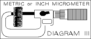
1. By using a micrometer or caliper;
Determine the major diameter (actual
outside diameter) of the male screw thread.
The major diameter may be
measured in decimal inches or millimeters.
Note that the major diameter
value is slightly undersized for female thread clearance, but the major
diameter is never greater than the nominal size of the male thread.
(see diagram).

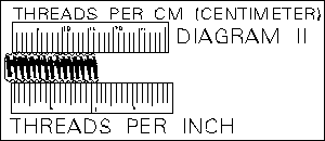
2. By using a rule or caliper, determine the number of threads per inch.
Or if available, a more accurate method is to use a pitch gage or a thread gage.

note: to properly identify a thread, you must have both a diameter
measurement and a pitch value, or thread per inch value.
3. Go to the appropriate size range of section (a).Check the basic major
diameter columns;
Locate the closest measurement in either the appropriate
millimeter (mm) or decimal inch column for the nominal diameter that you
have measured in step one.
Move across the row until you have found a match
for the threads per inch or pitch measurement from step two.
4. If there is only one thread in this row with your pitch or thread per
inch value, then the thread is now identified.
However, if there is more
than one thread in this row, you will have to determine the angle of the
thread for a final identification.
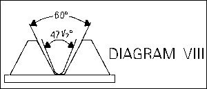
For example, a metric screw pitch gage
will readily show the difference in thread angles between 'BA' (47 1/2
degree) threads and metric (60 degree) threads.
|

|
Tap drill formula for metric 60 deg. threads;
nominal o.d. of thread (major diameter) - pitch = tap drill size.
(note: this formula will
yield approximately 68% - 77% of thread.)
Example: to find the tap drill
size for an m10 x 1.5 thread. 10 (o.d.) - 1.5 (pitch) = 8.5 mm (tap drill
size). |
|
How to calculate the approximate nominal major diameter
(o.d.) of the metric male (external) thread when only the female (internal)
metric thread is available for measurement.
1. Measure very carefully the pitch (p) using a thread pitch gage, or
any other type of measuring tool which will give an accurate reading for
pitch.
2. Multiply the factor value: (f)=1.0825 by the pitch (p) which yields
result (r). f x p = r.
Example: 1.0825 (f) x 1.75 (p) = 1.8944 (r)
3. Measure very carefully the (i.d.) inside diameter (minor diameter) of the
female metric thread using an internal micrometer, internal caliper, or
gage pin.
4. Add the measured value for the inside diameter (i.d.) to the result (r)
which will yield the nominal major diameter (o.d.) of the female thread.
i.d. + r = o.d. example: assume measured value 10.1036 (i.d.) + 1.8944 (r)
= 12 (o.d. or approximate nominal major diameter). |
|

